Flexible Cables (FC)
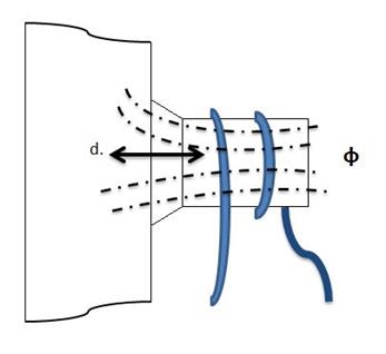
When a single conductor is used, the magnetic field reduces rapidly at increasing distance from the conductor; this restricts the production of an adequate test area with a sufficiently constant magnetic field. If the current is made to flow in the same direction through conductors spaced some distance apart, a relatively constant field is produced.
Flexible cable techniques can be used on a considerable variety of component shapes.
Configurations used are normally obtained with a heavy insulated flexible cable which is placed
through, on or around the specimen. A current passed through the cable will then induce a
magnetic field into the test piece. Unlike most MT equipment titles, which also give information
as to a longitudinal or circular magnetic field is generated, flexible cables only relates to the
equipment and a more specific title must be used to imply the type of induced field generated.
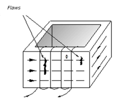
Discontinuities lying parallel to the cable will be the most readily detected. On complex shapes the position and technique in which the cable is wound may have to be found by experimentation to ensure an adequate field in all areas.
One technique of test utilising flexible cables is the adjacent cable technique. This technique of magnetisation requires the material being tested to be in close proximity to a current flowing in one direction.
The return cable for the electric current must be arranged to be as far removed from the inspection zone as possible and, in all cases, this distance should be greater than 10d.
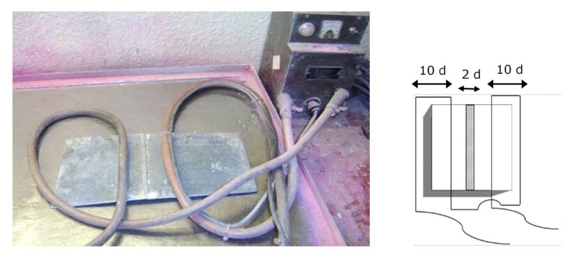
BS EN ISO 9934-1 quotes d as half the inspection area, whereas BS 6072 states d as the width of the inspection area.
BS EN 9934-1 quotes:
Where:
- NI = ampere turns
- H = tangential field strength
When testing radiused corners on cylindrical components or branch joints, e.g. stub to header welds, the cable may be wrapped round the surface of the component or the branch, and several turns may be bunched up in the form of a closely wrapped coil. In this case, the surface inspected shall be within a distance, d, of the winding.
Advantages of flexible cable techniques include:
- AC or DC fields.
- AC energised equipment may be used for demagnetisation operations.
- Large areas inspected with each set-up.
- No poles to attract magnetic particles.
- Field strength can be altered.
- Predictable field strengths.
Disadvantages include:
- Cumbersome long heavy cables required.
- Longer setting up times.
- Heavy transformers required for large amperages.
- Expensive equipment.